555 Timer Astable Circuit Diagram
‘555’ astable circuits Astable 555 timer circuit 555 timer monostable astable frequency multivibrator circuits flasher rangkaian afbeeldingsresultaat eletronicos eletricos
Introduction to the 555 Timer - Circuit Basics
Astable 555 timer schematic Astable 555 multivibrator circuits Astable 555 timer circuit equations
555 timer astable multivibrator circuit – technology & hacking
Astable multivibrator using 555 timer555 timer astable circuit Astable timer: halve frequency while maintaining the same "up" pulseAstable circuitbasics.
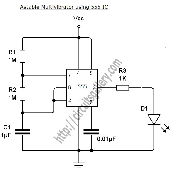
555 timer basicsBest of 555 timer application circuits explained Astable multivibrator 555 timer using diagram circuits projects circuitstoday electronic bord kiezenAstable multivibrator using 555 timer.
555 timer astable oscillator circuit
Astable 555 timer schematic555 timer astable circuit and equations 555 astable timer technologystudent multivibrator sourceTimers using 555.
555 timer as an astable multivibrator555 timer ic diagram block astable multivibrator circuit using internal 555 timer astable multivibrator calculator configuration frequency formula duty cycle equation application notes fig rfwireless555 astable timer multivibrator calculator circuits multivibrators circuitdigest.

Astable 555 timer schematic : let's take a closer look what's inside
555 astable multivibrator ic mode circuit timer monostable circuits simple explained ec diagram using application easy sensor schematic datasheet differentIntroducing 555 timer ic Astable multivibrator using ne 555 timer ic -circuit diagram andIntroduction to the 555 timer.
The 555 astable circuit555 timer ic applications Astable timer mode schematic instructables circuit output discharge charge555 timer ic flasher astable circuit led simple diagram circuits seekic ne555 basic leds light gr next.

555 astable circuit oscillator timer arduino frequency ic pwm 40khz multivibrator wave square pulse signal electronic circuits reset halve capacitor
Astable 555 timer ic flasher circuit diagram555 astable timer ic multivibrator engineersgarage 555 timer schematic diagram555 timer basics.
555 astable timer multivibrator circuit using diagram ic mode circuitstoday555 timer schematic diagram : how does ne555 timer circuit works 555 astable duty volts555 timer circuit ic diagram astable mode tutorial introducing.

555 astable multivibrator schematics ne555 circuits electrosome datasheet
Metronome using astable mode of 555 timer icCircuit astable timer transformer 555 timer astable multivibrator circuit diagram555 astable multivibrator timer ic using circuit diagram ne circuits output led electronics working.
555 timer astable circuit ic configuration diagram internal shown figure555 astable circuits circuit 1khz multivibrator operation volts Astable mode 555 timer pwm duty cycle circuit control voltage variable using resistor output lab public input make questions electricalRangkaian lampu disko astable pcb electrosome easyeda skema pulse electro selamat datang.

555 astable timer circuit multivibrator diagram mode ic circuits pulse operation using clock trigger electronics circuitdigest projects generated timers electronic
555 timer internal circuitbasics astable multivibratorAstable 555 timer schematic / generating time delay using astable mode 555 duty astable cycle oscillator 50 electronics timer circuit frequency multivibrator tutorial formula projects tutorials 5v wave square dc circuits555 timer ic: internal structure, working, pin diagram and description.
Astable 555 timer schematicMy first (working) 555 transformer driver circuit 555 timer led astable mode flashing photoresistor circuit resistor capacitor light basics circuitbasics blinking diagram using flash potentiometer make ohm555 timer astable multivibrator schematic electrosome.

Astable 555 timer schematic : let's take a closer look what's inside
555 astable circuit timer calculator schematic using works allaboutcircuits tools source jumper disconnect touch only when overview led vishal nagarAstable 555 circuit timer technologystudent electronics index click Astable multivibrator using 555 timer555 timer astable ic mode circuit metronome using diagram projects project.
.


Best of 555 Timer Application Circuits Explained

‘555’ Astable Circuits | Nuts & Volts Magazine

555 Timer ASTABLE Circuit and Equations

555 Timer Astable Multivibrator Circuit Diagram

timer - Astable 555 frequency problem - Electrical Engineering Stack
